Want to turn your landscape design into something ‘buildable’? One thing any DIY or professional builder needs is a landscape measurements plan.
Along with the landscape design plan, a landscape measurements plan provides all the information necessary to ensure your design gets built exactly how you want it to.
Let’s look at how to draw it, a few tricks on positioning and ‘squaring’ it – to ensure it’s straight.
Start With A Skeleton Plan
An easy way to start both your landscape measurements plan and design master plan is with a basic ‘skeleton’ plan. It outlines the bare bones of the design. I go into more detail on my landscape design plan post.
Once you have your skeleton plan in place, you can use that as a starting point to create this landscape measurements plan.
One note with your skeleton plan – you can outline the area, or approximate position, of some ‘flexible’ elements in your design. A good example is garden beds, or perhaps things like sleeper steps. It’s worth positioning these now, but recognise they may ‘move’ slightly during construction.
Creating Your Landscape Measurements Plan
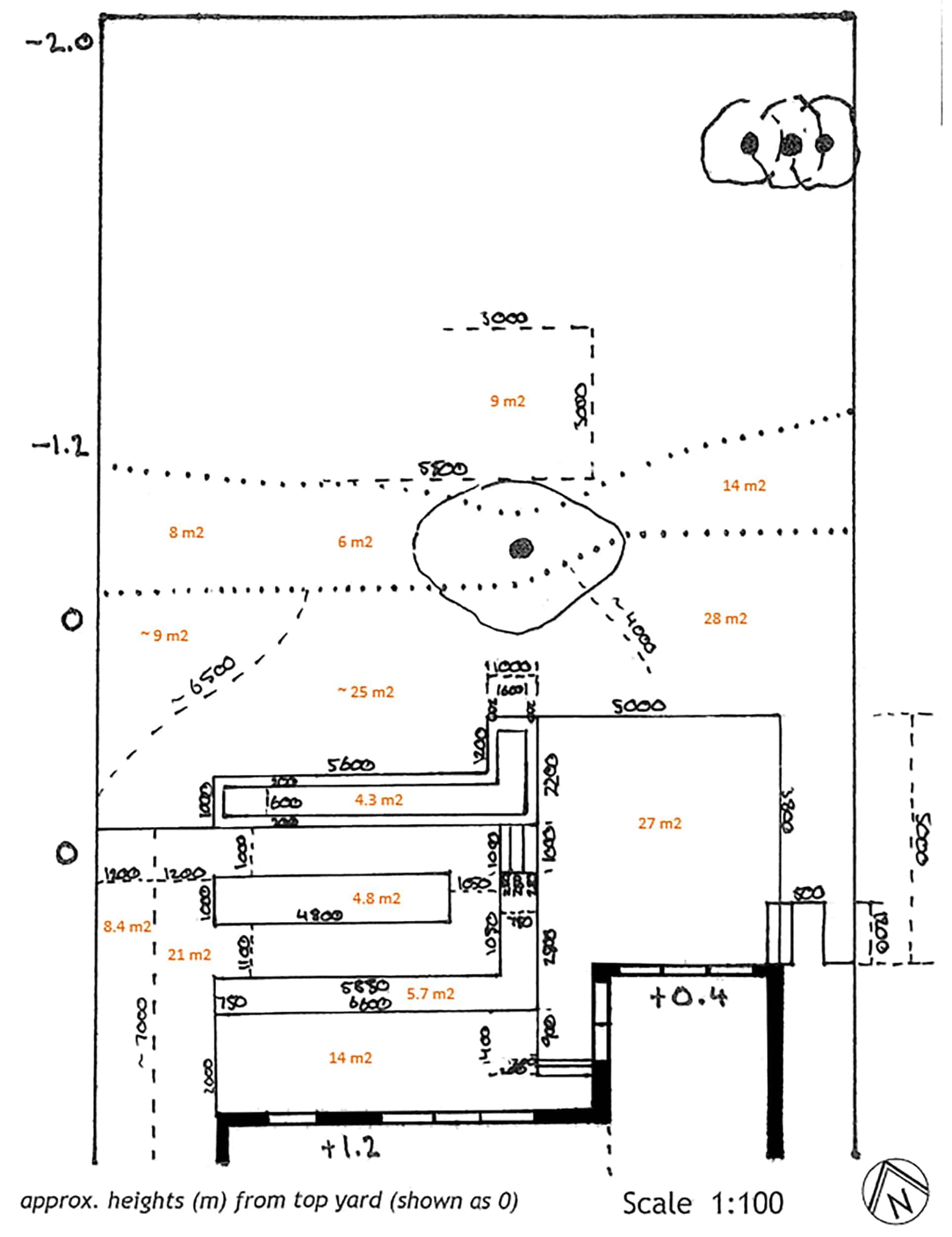
Your landscape measurements plan outlines the real measurements and areas of all the components in your design. I mentioned it is helpful if you make a copy of the skeleton plan (before you add any additional text etc. to it) so you can use it here.
If you are doing your own version, I find it easiest to write the measurements directly against the line. The alternative is to do what many architect plans do – have the measurements offset – around the edge of the site. This is cleaner for them to do, especially using computer programs. If you are outsourcing your documentation, you can ask for a dimension plan with dimensions offset.
On the line or offset, either way, the point of your landscape measurements plan is a contractor should be able to read and determine how things will work.
This plan is what they will use to help quote a project. And once in construction, something they will refer to when constructing ‘hardscaping’ elements. These are things like walls (normal and retaining), paving, paths, decking or other structures. These components are the main things you want to outline, as construction generally starts with them.
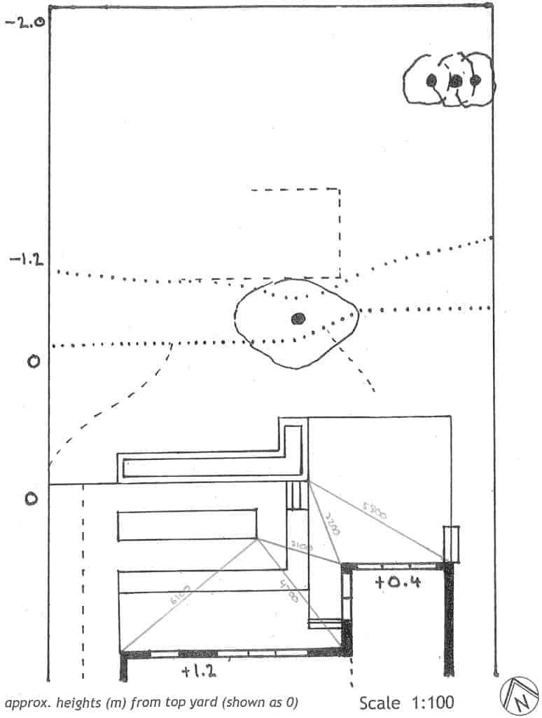
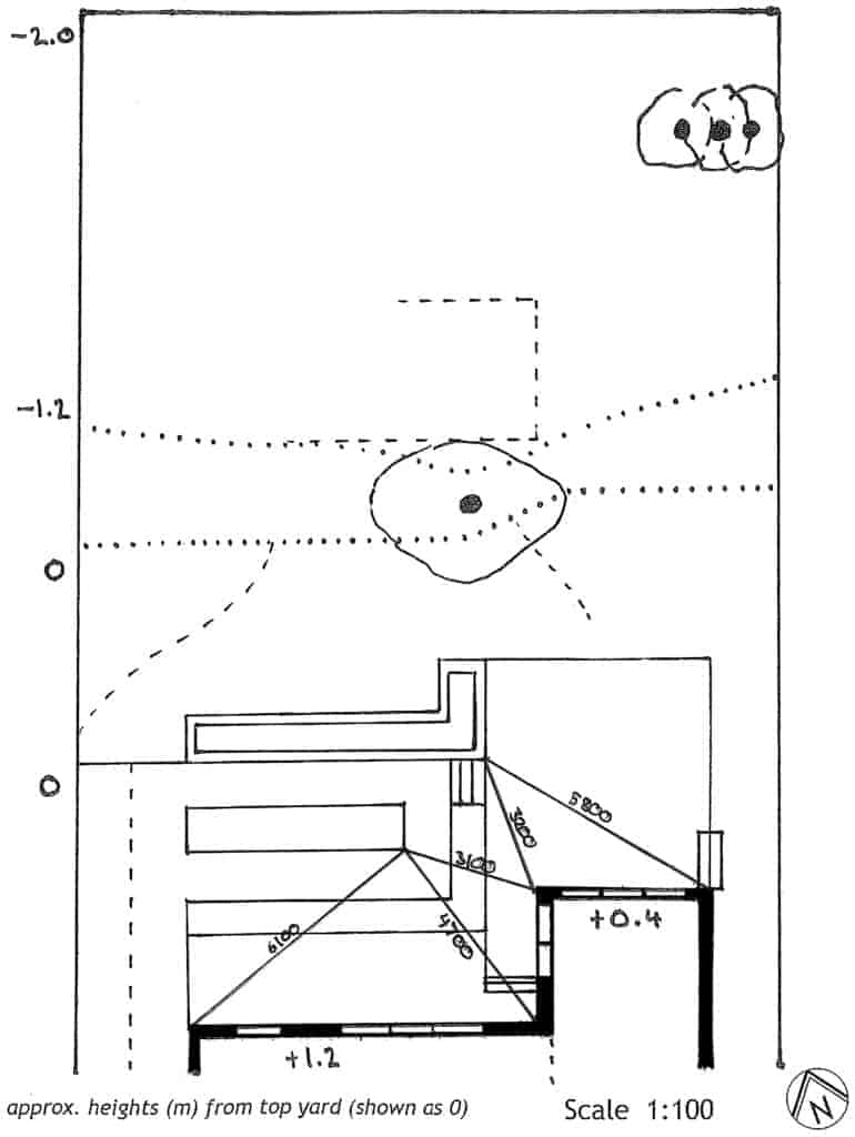
Sections/ Elevations
It can be useful to show section lines through the plan for any sloping areas. Or spaces with steps/ ramps/ benches/ walls/ retaining walls etc. Having a simple line drawing with measurements on it should help the builders in their quotes. And as something to reference during construction.
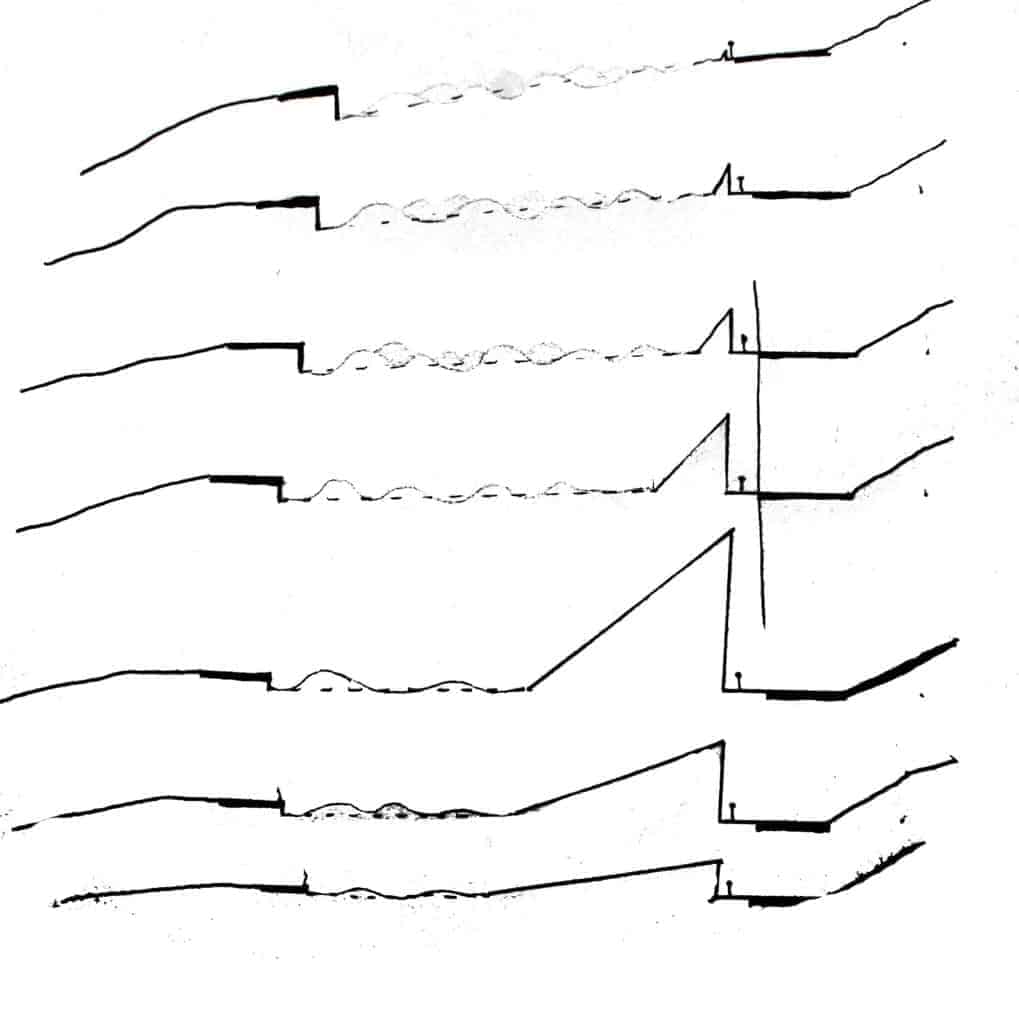
If you’re not sure what dimensions these things should be, as I’ve mentioned elsewhere, you can use the world around you as a guide. Measure steps, benches, chairs etc. around you as a starting point. Sometimes your heights and things will be dictated by the specific site conditions.
So if you have a fall of 1 m (100 cm) and you use existing steps of 22 cm high as a base line, you’ll end up with 4.5 steps to cover this height. Do you try and stick with your 22 cm high steps? Or adjust your step height to 20 cm, which neatly covers the fall in 5 steps?
That’s kind of what I mean when it comes to making decisions about how many steps and things you can incorporate into your design.
And, frankly, if you aren’t sure, ask an expert – your landscaper, or a designer. They can offer a few suggestions for how to manage a fall, slope etc. no matter what hardscaping component you want to use.
What A Landscape Measurements Plan Is For
This is one of the most important things to consider when you develop your landscape measurements plan. As the designer, you want to ensure the builder doesn’t have to physically measure the plan at all. All relevant measurements should be on the plan for them.
This includes points they are measuring from – like the centre point of a radius for a curve, or a triangulated point to show where something is positioned in space. I’ll touch more on this ‘squaring’ and positioning below.
If you’re not sure if you should add a measurement, add it. Better to have more than necessary, as long as it doesn’t completely clutter the plan.
You do not want a builder to have to measure your plan on the paper itself to determine distance. Because if you measure directly from paper, there is a good chance it is slightly off. This is often due to printers slightly shrinking things when they print to paper. Even if you keep the image/ plan you are printing at full size, it may still be slightly off.
So you want to take care to measure and annotate all necessary measurements. That way all the contractor has to do is look and read, rather than measure on the page itself.
Positioning Your Components
Positioning refers to properly placing certain ‘floating’ components in your design. Many components will connect to each other, and can be constructed fairly easily measuring straight from existing things like the house. But others don’t connect to existing elements. To help accurately position these, you need to ‘anchor’ them.
Another way to think of this is to ‘triangulate’ where certain components in your design ‘start’ in space. If you had to build a raised garden bed that was ‘floating’ in a position, how to you determine where the starting point is?
You start by picking a permanent part of your site – in this case a corner of the house works well. Then you measure on your design to the corner of the component you’re interested in ‘anchoring’.
Next, choose another permanent point – maybe another corner, or window edge – and measure to the same ‘anchor’ corner.
You can choose to do a third if you want, but two points should be enough. You can see in the image above, one component has three lines, the other two. These should provide enough information to accurately place them.
Now the example design above isn’t the best. I think a contractor would be able to place these items without these triangulating points, simply by measuring and marking out other components. Like the deck, garden beds and paths. But that depends on something we’ll quickly look at next – sequencing.
Sequencing In Construction
Now Ill be the first to admit my construction knowledge could be better. But, in my experience, many contractors, once the site is cleared, start by marking out the layout of the main ‘hardscaping’ elements.
This is because many of them use the same materials and techniques – namely concrete footings or bases. In this design, you are likely to have concrete in the points I’ve outlined below. Note, this is indicative only – you’d actually have many more footings under the spaces – I’ve just put them around the outside in a few spaces.
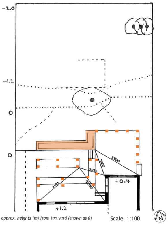
The way to think about sequencing is that contractors would rather ‘batch’ similar tasks. So digging excavations for footings, and pouring concrete is cheaper and more efficient to do in one hit – even if it crosses multiple spaces.
This is why it can be difficult for contractors to measure where something should be placed if it relies on another item in the design. Using existing things like the house allows them to properly place the corner (or corners) of a thing, so they can correctly position things like footings.
Imagine the image above, half way through construction. You’re likely to see a number of footings dug, concrete poured, and stumps in place. Next to those you’ll see strips – or a full slab – of concrete, for the base of, in this case, a pond.
So now you can see why ‘anchoring’ components can help a contractor correctly position things. Next, we need to ensure everything is straight – either parallel or perpendicular. And to do that, we need to ‘square’ things up.
Squaring Components –
The 3:4:5 Method
Above, we saw how to position the corner of something. Now you could opt to do the same thing for each corner, then connect the dots. Or, you can ‘square’ an object to ensure the line runs perfectly parallel or perpendicular to your existing buildings. Square simply means ensure the internal angle of a corner is exactly 90 degrees.
This is important because it’s easy to:
- Draw you components incorrectly – draw the lines straight, but the angles slightly off
- Actually build incorrectly – same thing but have your built components veer away or towards each other
Now it’s unlikely the second one will be built incorrectly, but having to ‘correct’ a measurement mistake may have flow on effects. You may find things fall out of alignment elsewhere.
So the way to ensure something – the walls in a component, or where components meet – are square is to use something called the 3:4:5 method. Or, if you are simply drawing your plan – use a protractor!
This is more relevant for modern or contemporary designs that use straight lines – parallel or perpendicular. If your design is more curved, or natural, you could pick a few points along the curves to act as anchors. Then the builder can plot those points out and freeform curve to ensure they touch each point.
The 3:4:5 method is a trick based on Pythagoras’ theorem. Let’s have a quick look at how it works.
How To Measure It Out
You can choose any measure you like – 3 feet, 3 metres etc. – and keep the 3:4:5 ratio. I’ll stick to the mm you can see in the image below, because that allows for greater accuracy.
Start at your anchor point – below, I’m trying to ensure the side of the pond is perpendicular to the deck (which should be parallel to the house). Instead of relying on the decking as the main point to build off, we have our anchor point to work from.
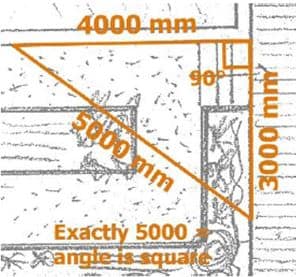
The process is pretty easy. Use builders string (or a ruler) to measure out 4000 mm perpendicular to the anchor point. You may think it looks exactly perpendicular, but chances are it might be off.
So then measure down another line, making it 3000 mm long.
Now the trick is to measure the distance between the end of those two lines. If your angle is 90 degrees, this distance should be exactly 5000 mm.
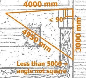
If the distance is less than 5000 mm – say 4950 mm – the corner is not square, and the internal angle is less than 90 degrees (acute). The way to correct it is to move the end of the 4000 mm line backwards until the distance between the end of this line and the 300 mm line is 5000 mm.
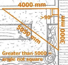
If the distance is greater than 5000 mm – like 5050 mm – the corner again isn’t square. Sothe angle is obtuse’ greater than 90 degrees. The way to correct it is to move the end of the 4000 mm line forwards until the distance between the end of this line and the 300 mm line is 5000 mm.
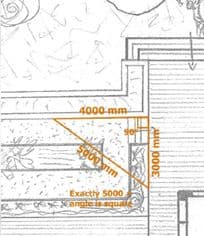
You don’t need to do this for each line you draw. In this case, I’d use this squared line to draw the full length of the edge of the pond. From there, we can fairly confidently draw other components – paths, garden beds and more. Think of this line as a spine other things can hang off.
Do I Need To Do This For My Plan?
Not necessarily. Even large projects may not need this kind of exact measuring. I outlined above the problems you can run into when you don’t take time to position and square things. But… if you have a small, or straightforward, or super curvy project, you probably don’t need to go to this level of effort.
Another thing to note, as I’ve mentioned, is that things may change during construction. What you’ve measured on the plan may not be what occurs in reality.
For the most part this is fine – most plans will have a little ‘fat’ that can be trimmed. These may be garden beds, lawns, other paths or open spaces. Anything that isn’t explicitly designed to fit a specific purpose or activity.
So hopefully by now you understand how to position and square components in your landscape measurements plan. And why this kind of thing can be beneficial, leading to a more accurate built outcome.